DEGREE
Index
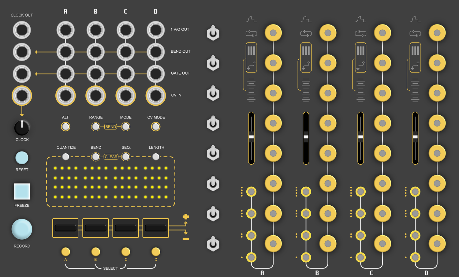
Legend
| Label | Description |
|---|---|
| 1V/O Output | Outputs 1 volt per octave |
| GATE Output | Outputs +5V gate / trigger signals |
| CV Input | Quantize external CV into 1v/o signals | VCO Frequency detection for auto-calibration |
| Bender CV Output | Outputs a control voltage relative to the position of a Bender component |
| Channel Select Pad | Selects a channel You can select multiple channels at once. |
| Freeze Button | Freezes all playback. |
| Reset Button | Resets all sequences. |
| Length Button | Adjusts the length of a sequence. |
| RECORD Button | Enables recording for all touch and bend events (for all 4 channels). |
| Scale Selection Switch | A 3-stage toggle switch used scale selection. |
| CV Mode Button | Toggles between MONOPHONIC MODE and QUANTIZER MODE |
| Glide Control | Controls how much slew/portamento/glide is applied to the 1v/o OUTPUT (when transitioning between scale degrees). |
| Octave Touch Pad | Capacitive touch pad for setting the active octave for a channel. |
| Degree Touch Pad | Capacitive touch pad for setting the active degree for a channel. |
| Clock Input | External clock source input. |
| Clock Output | Internal clock source output. |
| Global Gate Output | Sums all Gate events into one output |
| Global Bender Output | Sums all Bender CV into one output |
| Bender | bi-directional actuator that bends up / down using the force of your finger. |
| Bender Mode | Sets the Bender mode for the selected channel (via Channel Select Pad). |
| RANGE Button | Sets the Pitch Bend range applied to the 1V/O Output when using the Bender components. |
| Quantize Button | Quantizes a sequences touch events to the selected quantization grid. |
| ALT Button | Hold down to access alternate button functions (labeled in gold). |
| Clear Touch Sequence | Clears all Touch Sequences. |
| Clear Bend Sequence | Clears all Bend Sequences. |
| Sequencer Display | Displays the sequence progress and the occasional nested setting. |
| Clock Potentiometer | Sets the internal BPM of the module. |
| Tempo LED | Indicates the tempo (in quarter notes) of the internal (or external) clock |
Introduction
Bender is a performance oriented VCO controller / sequencer designed around custom manufactured illuminated capacitive touch pads. The modules main purpose is to control the pitch of 4 independent VCOs by interacting with the touch pads. Additionally, the module can auto-calibrate your VCOs 1v/o tracking, quantize incoming CV, output gate/triggers, apply analog slew/portamento, and has 4 custom Bender components for pitch bend and ratcheting effects.
The module contains 4 identical Channels, with each channel consisting of the following hardware:
- Degree Touch Pads: Capacitive touch pad for setting the active degree for a channel.
- Octave Touch Pads: Capacitive touch pad for setting the active octave for a channel.
- Glide Control: Controls how much slew/portamento/glide is applied to the 1v/o OUTPUT (when transitioning between scale degrees).
- 1V/O Output: Outputs 1 volt per octave
- GATE Output: Outputs +5V gate / trigger signals
- CV Input: Quantize external CV into 1v/o signals | VCO Frequency detection for auto-calibration
- Bender: bi-directional actuator that bends up / down using the force of your finger.
- Sequencer Display: Displays the sequence progress and the occasional nested setting.
The module has a column of 8 3-stage toggle switches for setting the "scale".
The module is internally clocked with a resolution of 96 pulses per quarter note (PPQN), allowing you to record sequences of Touch Events and Bend Events and play them back in real-time.
Channel Modes
At any given time each channel operates in one of two modes. Monophonic Mode or Quantizer Mode.
You can toggle between a channels modes by holding your finger on a Channel Select Pad and pressing the CV Mode Button.
Monophonic Mode
This is the most basic of modes.
For each channel, only one touch pad will be illuminated at a time.
Touching any of the touch pads pads immediately outputs the respective scale degrees voltage to that channel's 1V/O Output.
Additionally, when a touch pad is touched the corresponding channels GATE output is set to HIGH (+5V), and on release set back to LOW (0V).
Quantizer Mode
In quantizer mode, all 8 degrees become available options for incoming CV signals to get latched to. If a touch pad is illuminated, incoming CV can be latched to it.
When a CV voltage latches to an active degree, that touch pad LED will dim; the 1V/O Output gets updated; and a trigger signal will appear at the GATE Output.
Sequencing
Both Monophonic Mode and Quantizer Mode have the ability to enter a third mode: Sequencer Mode. When in sequencer mode, the module will record touch and bend events, map them to a 32 step (96 PPQN) grid, and play them back in real-time.
To enable recording, press the RECORD Button. The button will illuminate RED to signify recording is now active / enabled.
When RECORD is enabled, each channel will constantly listen for new Touch Events and/or Bend Events and add them to the actively running sequence, while simultaneously playing back any pre-existing touch or bend events.
As a sequence plays back, new events will overdub / overwrite previously existing events (should they overlap).
To disable sequence recording, press the RECORD Button once more. If any Touch Events or Bend Events occurred on any of the channels while RECORD was enabled, then those channels will remain in Sequencer Mode and continue to playback the recorded sequence. If during this process a channel didn't receive any new events, this channel will be reverted to its previous mode (prior to enabling record).
ALT Firmware: In the alternate firmware, sequence recording works a little differently.
Pressing the RECORD Button will "arm" sequence recording (LED will Flash / blink). Recording only gets enabled (or disabled) once beat 1 of the bar rolls over.
Note: Although recording theoretically doesn't begin until beat 1 occurs, there is a short grace period no longer then a 16th note prior to beat 1 which will listen for touch events and include them in the recorded sequence (they get quantized to beat 1 of the bar).
Sequencing in Monophonic Mode
To add an event, just touch one of the channels touch pads while record is enabled. On touch, the sequencer sets the GATE OUT HIGH, and on release sets the GATE OUT LOW. If a new event overlaps with any pre-existing events, the new event will take priority and any pre-existing events will be permanently over-written.
Sequence override:
During playback of a sequence, should record be disabled, interacting with the touch pads will override the playback of a sequence.
On touch: stops playback of sequence, sets the GATE Output HIGH, and outputs the 1VO value associated with that touch pad.
On release: sets GATE Output LOW, and resumes playback of sequence
When freezing a sequence, the sequence will continue to progress through its steps in the background. This way, the sequence will "pick up where it left off", so to speak.
Sequencing in Quantizer Mode
In this mode, a sequence contains a series of Active Degrees "snapshots".
Touching a pad will either add or remove that degree/octave from an Active Degrees list, then insert a "snapshot" of this list and insert it as a new event in the sequence. As the sequence progresses, it will update the Active Degrees list based on each events "snapshot".
Gesture: If you hold your finger on a channels Channel Select Pad while a sequence is playing back in Quantizer Mode, interacting with the touch pads will override the incoming signal at the CV Input and output the 1VO value associated with that touch pad.
Sequence Length
The length of a sequence can range from 2 steps to 32 steps. Each LED in the sequence display accounts for 2 steps.
To adjust the length (number of steps) of a sequence, press the LENGTH button. The Sequencer display will illuminate the length of each channel's sequence. You can now use the BENDERs to increase or decrease the length of a sequence (by pushing / pulling the BENDER up or down). Presently, you can only have sequence lengths of even division. (ie. 2 steps, 4, steps, 6 steps, 8 steps, etc.)
NOTE: The Sequencer Display uses 16 LEDs to represent the 32 steps of a sequence.
ALT Firmware: The sequence length is measured in bars instead of steps. For example, if the Time Signature is set to 4/4, the sequence length would either be 4 steps, 8 steps, 12 steps... with a max of 32 steps.
Quantizing a Recorded Sequence
Using the Quantize Button, you can quantize a sequences touch events to a grid of quarter notes, 8th notes, 16th notes, 32nd notes, and 64th notes.
You can set a channels quantization amount using the Quantization Grid UI. To enter this UI, hold down the ALT Button + RANGE Button.
After performing this gesture, the LEDs of each channels degree touch pads will start flashing at varying rates. The rates at which each LED is flashing corresponds to the level of quantization.
For example, the bottom most LED will be flashing at the same rate as the Tempo LED. Selecting this value will set the quantization amount to "quarter notes".
Once the Quantize Button is pressed, the firmware will iterate through each active sequence of touch events (for every channel) and snap those events to whichever Quantization Grid presently selected.
If you only want to quantize a particular channel, hold your finger on one of the Channel Select Pads before pressing the Quantize Button. This will only quantize that channel.
Clocking ⏰
The internal clock ranges from 20 BPM up to 240 BPM, and is set using the Clock Potentiometer.
If you want to use an external clock source for the DEGREE, plug the external clock signal into the Clock Input jack and turn the Clock Potentiometer all the way to the left.
NOTE: The clock resolution works best when sending the DEGREE 1PPQN (quarter note pulses).
Scale Selection
Logic and Theory
The DEGREE is very muched centered around the 12 notes of western music.
In western music, a scale usually consists of a total of 7 notes, but if you were to include the upper octave you would get 8 notes (ex. C, D, E, F, G, A, B, C).
The DEGREE offers the option to build such a scale using the 8 Scale Selection Switches.
Building a scale
The DEGREE contains a series of 8 scale degree switches which can be used to construct a common scale between all 4 channels.
Each position of a toggle switch represents a single semitone. If you change the position of a switch upwards, all 4 channels across the horizontal axis will increase their pitch by one semitone. If you go downwards, then it will decrease their pitch by one semitone.
For example, if all 8 switches are in their middle position, the scale degrees of each channel will be seperated by a whole tone (two semi-tones). In this state, you get what is called a "whole tone scale".
You can adjust the position of the switches to create major scales, minor scales, and everything in between.
If musical theory isn't your thing, use the following switch configurations to get a major or a minor scale (and everything will sound nice 🌈):
Major Scale
| Switch | Position | Scale degree |
|---|---|---|
| 8 (top) | CENTER | Major 2nd |
| 7 | DOWN or CENTER | Major 7th or Tonic octave |
| 6 | DOWN | Major 6th |
| 5 | DOWN | Perfect 5th |
| 4 | DOWN | Perfect 4th |
| 3 | CENTER | Minor 3rd |
| 2 | CENTER | Major 2nd |
| 1 (bottom) | CENTER | Tonic |
Minor Scale
| Switch | Position | Scale degree |
|---|---|---|
| 8 (top) | UP or CENTER | Either a Major 2nd or a minor 3rd |
| 7 | CENTER | Tonic octave |
| 6 | CENTER | Minor 7th |
| 5 | DOWN | Perfect 5th |
| 4 | DOWN | Perfect 4th |
| 3 | DOWN | Minor 3rd |
| 2 | CENTER | Major 2nd |
| 1 (bottom) | CENTER | Tonic |

The Benders 👌
Each of the four channels hosts a dedicated Bender component to act as a conduit between your finger and your modular system.
It can be used in a variety of ways to modify the various outputs of the DEGREE, as well as provide a modulation source for other modules via its dedicated Bender CV Output (+-8V).
As mentioned, there is a variety of modes a Bender can be in at any one time. It can either be in Pitch Bend Mode, Ratchet Mode, Pitch Bend Mode + Ratchet Mode, or simply just "off".
NOTE: regardless of which mode a Bender is in, it will ALWAYS output the raw CV value. You cannot disable this. (and why would you?!)
Bender Modes
Pitch Bend Mode
When the 🔃 symbol is illuminated, the Bender is in "Pitch Bend" mode. In this mode, the Bender will apply a pitch bend effect to the 1V/O Output of that channel.
Pitch Bend Range: When holding down the RANGE Button, you can set the range in which the Bender effects the 1V/O Output (in semi-tones). There are 8 possible semi-tone ranges: 1, 2, 3, 4, 5, 7, 10, and 12 semi-tones.
Ratchet Mode
When the ⏸ symbol is illuminated, the Bender is in "Ratchet" mode, and will directly effect the GATE Output of the corresponding channel.
When pressing the Bender "upwards" (ie. towards the top of the module), then the GATE Output will begin creating trigger events at an increasing rate (quarter notes ^ 8th notes ^^ 16th notes ^^^ 32nd notes), etc.
When pulling the Bender "downwards" (ie. towards the bottom of the module), then the GATE Output will create trigger events that are triplets (at an increasing rate).
Pitch Bend + Ratchet Mode
In this mode, both the 🔃 and the ⏸ symbols will be illuminated, and thus execute the corresponding modes simultaneously.
OFF Mode
In the case when you don't want the benders effecting the GATE Output or the 1V/O Output, but still wish to use the raw Bender CV Output for modulating other modules in your system, use this mode.
Bender Sequencing
To record the movements of the Benders into a channels sequence, enable RECORD and start bending. The sequencer will record the raw CV values of the bender into the sequence, giving you the option to apply Pitch Bend or Ratchet effects after the fact, should you wish too.
Bender Calibration
The Bender components are very sensitive analog components. Each Bender component in your DEGREE is unique, and will react differently from its neighbor. Because of this, they must be calibrated by the on-board microcontroller to obtain the most stable and consistent operation.
To enter Bender Calibration Mode, hold down ALT Button and then press the Bender Mode. Once calibration has been initialized, the sequencer display will illuminate the top most and bottom most LEDs. When you see this, start push/pulling the Benders to their maximum bend ranges (as limited by the panel). When you have done this for all the benders, hold down ALT Button and then press the Bender Mode to exit the calibration process. The new calibration data will now be saved in the flash memory of the device and preserved between power cylces.
NOTE: You should only need to do this once, but it would be worth while to re-calibrate your benders whenever you relocate your modular system - as the temperature of the air does effects the sensitivity of the analog sensors attached to the bender components.
Bender Replacement: Should any of your Bender components become faulty, please contact me and I will provide a replacement. You only need a screw driver to replace a Bender component yourself 🙂.
VCO Calibration
Analog VCOs are notoriously difficult to calibrate. They are very sensitive to temperature, humidity, and other environmental factors which ultimately causes imperfect pitch tracking (requiring frequent recalibration).
The DEGREE has the ability to auto-calibrate the 1-volt-per-octave response of analog VCOs. By doing this, all four VCOs which the DEGREE controls will be in perfect harmony with each other, allowing for very large and lush chords across 5 octaves.
It does this by patching a simple feedback loop between the target VCO and the DEGREE's CLOCK input. The frequency of the VCO is detected at a variety of voltages provided by the DEGREE's 1VO output, and the DEGREE then uses this data to calculate the frequency of the VCO at any given voltage using exponential interpolation.
NOTE: To reset the calibration data for a channel to default, see the Settings and Gestures section.
Calibration Steps
To calibrate a VCO, follow these steps (read each step carefully!):
- Ensure your system has been powered on for at least 10 minutes to allow your VCO to "warm up".
- Turn the Clock Potentiometer to the center position.
- Patch the 1VO output of the target channel to the 1VO input of the target VCO
- Patch the output of the VCO into the Clock Input of the DEGREE (SAW, TRI, or SQUARE waves work best)
- Set the frequency of the VCO to a low value. The VCO should be oscillating at a frequency between 16.35Hz and 65.41Hz.
- Select the channel you wish to calibrate by holding down the Channel Select Pad, then press ALT Button + CV Mode Button to initialize calibration. Once calibration has been initialized, the target channels sequence display will illuminate indicating that the VCO is being calibrated.
- The calibration routine will run for a few seconds, afterwhich the calibration data will be saved to flash memory and preserved between power cycles.
- The display will flash a few times indicating that the calibration is complete.
NOTE: When calibrating multiple VCOs, it is VERY important to first ensure that all VCOs are set to the same frequency. The chosen frequency should be between 16.35Hz and 65.41Hz. If you do not set each VCO to the same frequency prior to calibration, the "initial pitch" of each VCO after calibration will very likely be different.
For example, if one VCO is set to 32.70hz (C1), and another is set to 34.65hz (C#1), then the initial pitch of the first VCO after calibration will be a semi-tone higher than the second VCO.
TIP: You don't need a tuner to set the frequency of your VCOs prior to calibration. You can just use your ear to ensure they are all set "nearly" to the same frequency. The calibration routine will take care of the rest.
NOTE: You should only need to do this once, but it would be worth while to re-calibrate your VCOs whenever you relocate your modular system.
NOTE: You can only calibrate one VCO at a time!
Settings and Gestures
For each channel, the following settings are stored between power cycles of the module:
- 1 V/O calibration data
- Bender calibration data
- Channel mode
- Bender mode
- Pitch Bend range
- quantize grid
- The recorded sequence (should one exist)
If you ever want to save or reset the current configuration of the module, use the following gestures 👇.
Config. Reset
Holding ALT Button + the Freeze Button will reset all of the the saved configuration data on the module. This includes the 1v/o calibration, the bender calibration, and the various channel settings to their default values.
VCO Calibration Reset
While holding one or more Channel Select Pads, pressing ALT Button + the Freeze Button will reset the 1v/o calibration data for all selected channels to their default values.
Config. Save
Holding ALT Button + the RECORD Button will save the current settings of each channel so you don't need to reconfigure things after a power cycle.
Firmware Updates
This web application is designed to update the firmware of OK200 Eurorack modules.
Just follow the steps below, and everything will be ok 🙂.
STEP 1: Are you using Google Chrome v61 or greater? 👀
In order for this to work, you are going to need to Install Google Chrome. It is the only way 🙏.
STEP 2: Download firmware file
Download one of the following firmware files:
| Firmware | Size | Download |
|---|---|---|
DEGREE Alt Firmware (Nov 2025) | 61 KB | Download |
DEGREE Firmware (Nov 2025) | 61 KB | Download |
DEGREE Alt Firmware (Jun 2023) | 61 KB | Download |
DEGREE Firmware (Jun 2023) | 61 KB | Download |
NOTE: The "ALT" firmware contains sequencing functionality that is different from the original firmware. The manual has been updated to reflect this (see Sequencing section).
STEP 3: Connect module to your computer / Google Chrome and prepare for upload
You now need to physically connect the module to your computer / laptop / tablet. Follow these steps:
- Power OFF your system.
- Bring your laptop over to your system (or bring your system close to your laptop)
- Remove your module from the case, but keep the power cable connected.
- Using a standard USB cable, connect one end of the cable to the associated USB connector on underside of the module
- Connect the other end of the USB cable to your computer
- Power on your Eurorack case / power supply. The module needs to be powered for the firmware upload to work. Once powered, it should be operating as usual.
- Now, on the underside of the module, there is a tiny black button and a tiny white button (near where the Benders are mounted)
- Press and hold down the BLACK button
- While the BLACK button is being held down, press the WHITE button
- The module should now be "frozen" (ie. clock LED no longer flashing, touch pads unresponsive). This is GOOD! The module is now in "BOOTLOADER" mode.
STEP 4: Upload firmware to the module
At this stage, we need to officially connect the module to the Google Chrome browser
1. Press this button.
2. A window should appear containing a list of all the available USB devices on your computer. Select the device named STM32 BOOTLOADER from that dropdown.
Device Status: Not connected
3. Using the file selector below, select the .bin file you wish to upload to the module.
4. Now press this button.
STEP 6:
Finishing up
- Once the upload process is complete, the module should automatically reset itself and start running the newly uploaded firmware
- Power off your Eurorack system / disconnect the power supply
- Gently remove the USB cable from the modules USB connector
- You can now mount the module back into your case and turn on the power.
- After the module powers up, you are going to want to calibrate the BENDER components (ALT + MODE)
- You are done!