Counterpoint
Eurorack performance sequencer.
👋 Introduction
coun·ter·pointˈkoun(t)ərˌpoint'
noun
1.Musicthe art or technique of setting, writing, or playing a melody or melodies in conjunction with another, according to fixed rules.
verb
1.Musicadd counterpoint to (a melody).
"the orchestra counterpoints the vocal part"
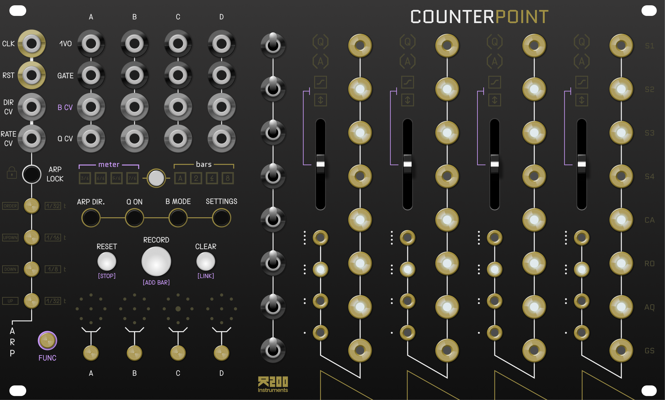
This is COUNTERPOINT. It is a Eurorack module designed to control multiple oscillators in a modular system, with the core focus being to keep each oscillator (or "voice") musically coherent with one another.
It uses four channels of brass touch pads (capacitive touch) to control the pitch of four independant oscillators (VCOs), all while containing them to a common musical scale.
The musical scale is set using a collection of eight 3-stage toggle switches intended to explore musical scales in an unopinionated way.
The module is very hands on and performative. It features a sequencer that allows the performer to capture harmonic progressions and ideas on the fly and play them back as sequenced loops which can be further manipulated in real time through a variety of gestures.
Counterpoint also features an arpeggiator, per channel CV quantization, and per channel pitch bend / portamento effects.
This manual will guide you through the various features and functions of the Counterpoint.
For more info on the name, check out this wikipedia page.
🔄 Inputs / outputs

The input / output jacks are split into two sections. On the right side there is a grid of jacks corresponding to each channel (channel A, B, C, D), and on the left side are jacks corrosponding to the clock transport and arpeggiator.
Channel in/out
The input / output jacks are arranged as a grid. Each column (A, B, C, D) in the grid contains the input / output jacks for a channel.
The rows of the grid corrospond to the type of input / output jack:
| Label | Description |
|---|---|
| 1VO | 1 volt per octave output (-1V to 9V range) |
| GATE | 5V gate signal |
| B CV | CV control over channel slew OR "pitch bend" of 1VO output |
| Q CV | When a channel is in Quantizer mode, the voltage present on this input will be quantized to the nearest scale degree |
Global in/out
Additionally, there is an isolated column for "global" CV control:
| Label | Description |
|---|---|
| CLOCK | A clock signal must be present here in order for time related functions to work. See the Clocking section for more information. |
| RESET | Reset any active sequences to beat one. (it will wait till the next quarter note occurs before resetting) |
| DIR CV | CV control over the direction of the arpeggiator. |
| RATE CV | CV control over the rate of the arpeggiator. |
⏰ Clocking
A stable clock signal is necessary for the module to function properly.
"Clocking" is the process of using an external clock signal to synchronize the module with the rest of your system.
Presently, the Counterpoint can only be clocked externally via the CLOCK input jack.
Ideally you will want to use a 1/4 note (quarter note) pulse signal at the CLOCK input jack. The onboard microcontroller will divide this signal into a 24 PPQN (pulses per quarter note) grid in order to achieve various time related functions (sequencing, arpeggiation, etc).
Note: The internal clock will never exceed 240 BPM nor go below 40 BPM (regardless of the clock signal present at the CLOCK input jack).
🎛️ Channel Modes
Each channel can be in one of three modes: MONOPHONIC mode, QUANTIZER mode, or ARPEGGIATOR mode.
Monophonic Mode
This is the default mode for each channel when the module is powered on.
In this mode, the module will output a precise voltage corrosponding to the last touched scale degree.
As long as a degree or octave pad is touched, that channels GATE output will be HIGH.
When a channel is in MONOPHONIC mode, both the [Q] and [A] symbols will be dimmed.

Quantizer Mode
In this mode, a channel will detect the voltage present on the Q CV input jack and remap that voltage to the nearest scale degree.
You can use the touch pads to activate/deactivate scale degrees and octaves, limiting the range of the 1VO output.
To enter a channel into QUANTIZER mode, press the Q ON button while touching the SELECT PAD for that channel. The [Q] symbol for that channel will illuminate.


Arpeggiator Mode
In this mode, a channel will arpeggiate all the currently touched scale degrees based on the active rate and direction of the Arpeggiator.
A channels [ARP] symbol will illuminate when the channel is in ARPEGGIATOR mode.

See the Arpeggiator section for more information.
🎼 Scale Degree Switches
The 8 toggle switches on the Counterpoint are what you use to contruct a common musical scale between all 4 channels. They logic behind them is centered around music theory, particularly the concept of "Counterpoint and Harmony". You don't need to know any music theory to use the module, but if you're interested in the theory behind it you can check out this wikipedia page.
Each position of a toggle switch represents a single semitone. If you change the position of a switch upwards, all 4 channels across the horizontal axis will increase their pitch by one semitone. If you go downwards, then it will decrease their pitch by one semitone.
For example, if all 8 switches are in their middle position, the scale degrees of each channel will be seperated by a whole tone (two semi-tones). In this state, you get what is called a "whole tone scale".
You can adjust the position of the switches to create major scales, minor scales, and everything in between.
If musical theory isn't your thing, use the following switch configurations to get a major or a minor scale (and everything will sound nice 🌈):
Major Scale
| Switch | Position | Scale degree |
|---|---|---|
| 8 (top) | DOWN | Tonic octave |
| 7 | CENTER | Major 7th |
| 6 | CENTER | Major 6th |
| 5 | CENTER | Perfect 5th |
| 4 | CENTER | Perfect 4th |
| 3 | UP | Major 3rd |
| 2 | UP | Major 2nd |
| 1 (bottom) | UP | Tonic |
Minor Scale
| Switch | Position | Scale degree |
|---|---|---|
| 8 (top) | DOWN | Tonic octave |
| 7 | DOWN | Minor 7th |
| 6 | DOWN | Minor 7th |
| 5 | CENTER | Perfect 5th |
| 4 | CENTER | Perfect 4th |
| 3 | CENTER | Minor 3rd |
| 2 | UP | Major 2nd |
| 1 (bottom) | UP | Tonic |

⤴️ Pitch Bend / Portamento

Each channel can apply one of PORTAMENTO or PITCH BEND to the 1VO output using the vertical sliders and the B CV input.
| Mode | Description |
|---|---|
| PORTAMENTO | Smoothly move between scale degrees |
| PITCH BEND | Converts the control voltage present on the B CV input to an unquantized value between 1 and 12 semitones (in both directions) |
You can toggle the BEND MODE of a channel by pressing the B MODE button while touching the SELECT PAD for that channel.
Both the SLIDER and the B CV input operate differently depending on which BEND MODE the channel is in.
In PORTAMENTO mode, the SLIDER sets the amount of time it takes for a channel to move between scale degrees, and CV at the B CV input will add or subtract from that time.
In PITCH BEND mode, the SLIDER acts as an attenuator for the control voltage present on the B CV input.
Note: the CV input range for the B CV input is -10V to 10V.
🎵 Arpeggiator

The ARPEGGIATOR is a tool that allows you to play back all of the currently touched scale degrees as an arpeggio at varrying rates.
To enable the arpeggiator, touch one of the four ARP RATE pads. As long as one of the ARP RATE pads is touched, any channel that was previously in MONOPHONIC mode will enter in to ARPEGGIATOR mode.
In this state, interacting with the TOUCH PADS of a channel will immediately play back the selected scale degrees as an arpeggio. The arpeggio will play back at the rate set by the ARP RATE pad that is currently being touched, and the arpeggio will progress in the direction set by the ARP DIR button.
As soon as you release the ARP RATE pad, all channels will revert back to MONOPHONIC mode.
If you wish to have a channel remain in ARPEGGIATOR mode without holding the ARP RATE pad, press the ARP LOCK button while touching the SELECT PAD for that channel (perform the same gesture to revert a channel back to its previous mode).
You can change the rate and direction of a specific channel while it is in ARPEGGIATOR mode by using the channel's SELECT PAD and the ARP RATE / ARP DIR pads.
Additionally, pressing the ARP LOCK button without a SELECT PAD being touched will keep the arpeggiator engaged for all channels regardless of whether the ARP RATE pad is being touched.
Note: Enabling / disabling the arpeggiator will only work if a channel is in MONOPHONIC mode. If it is in QUANTIZER mode, the arpeggiator will not be enabled / disabled.
Arp Rate
The rate of the arpeggiator can be set to quarter notes (1/4), eighth notes (1/8), sixteenth notes (1/16), or thirty second notes (1/32).
Additionally, if you hold the TRIPLET pad in conjunction with an ARP RATE pad, the arp rate will be set to a triplet of the selected note value.
To set the arp rate, touch one of the four ARP RATE pads. The arp rate will change based on the highest arp rate that is touched.
Arp Rate CV Control
The rate of the arpeggiator can also be controlled with CV via the RATE CV input (0V to 10V).
At slightly above 0V, the arp rate will be set to the quarter note value. As the control voltage increases, the arp rate will increase until it reaches its highest possible value of thirty second note triplets when CV is at 10V.
| CV Input | GATE Output Rate |
|---|---|
| 0V - 1.25V | 1/4 |
| 1.25V - 2.5V | 1/4t |
| 2.5V - 3.75V | 1/8 |
| 3.75V - 5V | 1/8t |
| 5V - 6.25V | 1/16 |
| 6.25V - 7.5V | 1/16t |
| 7.5V - 8.75V | 1/32 |
| 8.75V - 10V | 1/32t |
Arp Direction
The arp direction can be set to UP, DOWN, UP/DOWN, or ORDER.
To set the arp direction, press the ARP DIR button and use the ARP RATE pads to select the direction.
Arp Direction CV Control
The arp direction can also be controlled with CV via the DIR CV input (0V to 10V).
0-2.5V is UP, 2.5-5V is DOWN, 5-7.5V is UP/DOWN, and 7.5-10V is ORDER.
🧬 Sequencing

If you have not already noticed, there is a really large RECORD button on the module. This button is used to record interactions with a channels touch pads (and play them back as a sequence).
Recording a sequence
After pressing the RECORD button it will begin to illuminate red. This indicates all channels are primed for sequencing.
Once a channel is primed for sequencing, it will playback any touch events that occur on that channels touch pads. This includes both the OCTAVE and DEGREE pads.
As a sequence plays back, new events will overdub / overwrite previously existing events (should they overlap).
If this is not already obvious, each channel can be sequenced independently.
Note: Once a sequence is created for a channel, the meter of that sequence will be locked and no longer follows the active meter displayed on the panel.
For example, one channel can have a sequence playing back in a meter of 3/4, and another channel can have a sequence playing back in a meter of 4/4.
Sequence length and meter

Sequence length

A sequence's length is determined by both the BARS and the METER settings.
If BARS is set to [A], the sequence length will continue to increment (by bars, not steps) as long as RECORD is enabled.
If BARS is set to one of [2], [4], or [8], then the sequence length will be preset to that number of bars.
Additionally, you can append one bar to a channels sequence by holding down the corrosponing SELECT PAD and pressing the RECORD button.
How AUTO sequence length works: As long as RECORD is enabled and bars is set to AUTO, the length of a sequence will automatically increase in increments of one bar as time passes. Once you feel the sequence is long enough, you can press the RECORD button again to disable recording.
Sequence meter

A sequence's 'meter' is the number of beats in a bar. It can be set to [3/4], [4/4], [5/4], or [7/4].
To set the meter of a sequence, press the button between the BARS and METER display while holding down the ALT button.
Any new sequences will automatically be set to the active meter. Any existing sequences will not change.
To see the meter of an existing sequence, hold the SELECT PAD for that channel. The associated meter for that channel's sequence will begin to pulse/blink.
Sequencing in Monophonic Mode
When sequencing a channel that is in MONOPHONIC mode, all touch events to the OCTAVE and DEGREE touch pads will be recorded and played back as a sequence.
As long as RECORD is enabled, you can continue adding new events to the sequence.
If an new event occurs at the same time as a previous event, the previous event will be overwritten.
Additionally, all events which occur before a new event is "released" will be deleted / overwritten by the new event.
Sequence Override: If a sequence is playing back and RECORD is not enabled, interacting with the touch pads will override the sequence and output + hold the last touched scale degree. Releasing your finger will re-activate playback of the sequence.
Sequencing in Quantizer Mode
When sequencing a channel that is in QUANTIZER mode, touching a degree / octave pad will add a "snapshot" of the current active scale degrees (minus the one you just touched) to the sequence.
Sequencing with the arpeggiator
You can use the arpeggiator to add events to a sequence, but only when that channel is in MONOPHONIC mode.
The GATE associated with events created with the arpeggiator are treated as "trigger" events.
Clear a sequence
Pressing the CLEAR button will "clear" / delete all sequences.
If you want to clear a sequence for a single channel, press the CLEAR button while touching that channel's SELECT PAD.
Reset a sequence
Pressing the RESET button will reset the sequence, but not immediately. It will wait until the next quarter note occurs before resetting.
Stop a sequence
Holding FUNC and pressing RESET will stop all sequences on the next beat. The sequence will not continue to play back after it is stopped. To resume playback, press RESET again.
You can stop individual sequences by holding the SELECT PAD for that channel and pressing FUNC + RESET. To resume playback, press RESET again.
Quantizing a sequence
Pressing ALT + RECORD will "snap" all touch events in all active sequences to a grid of 32nd notes.
If you wish quantization to occur automatically, enter SETTINGS and make sure the AQ row is illuminated.
If you want to quantize only a single sequence, press the ALT + RECORD button while touching the SELECT PAD for that channel.
🔗 Channel Link
Counterpoint allows you to link several channels together so that one channel becomes the master, and the remaining (linked) channels the follower.
This means that when a master channel changes its output, any linked channels will also change their output to match the master channel's output.
This feature allows you to more easily create large sounding monophonic leads/basslines, as well as create dyad progressions between two channels (or triad progressions between three channels, etc.).
To link a channel, hold FUNC + SELECT PAD for the channels you wish to link and then press the CLEAR button.
The master channel is determined by the channel which was touched first.
To unlink a channel, hold FUNC + SELECT PAD for the channels you wish to unlink and then press the CLEAR button.
Note: the SLEW setting for a channel will always be independent of the linked channel, but any pitch bend CV will be syncronized between the linked channels.
Dyadic intervals
For each linked channel you can apply a dyadic offset to the master channel by interacting with the follower channel's degree pads. This means that a follower channel doesn't have to be in unison with the master channel. For example, you could have the follower channel output exactly a minor third above whatever the master channel is outputting.
The following table shows the relationship between the physical pad and the associated dyadic interval.
| Physical pad | Interval | Semitones |
|---|---|---|
| 1 (bottom) | Unison | 0 |
| 2 | Minor 3rd | 3 |
| 3 | Major 3rd | 4 |
| 4 | Tritone (♯4/♭5) | 6 |
| 5 | Perfect 5th | 7 |
| 6 | Minor 6th | 8 |
| 7 | Major 6th | 9 |
| 8 (top) | Octave | 12 |
Octave offsets
When a channel is linked, you have the ability to adjust the octave offset of any of the follower channels. This is done by interacting with the follower channel's octave pads while holding the FUNC pad.
| Octave pad | Octave offset |
|---|---|
| 1 | +0 octaves |
| 2 | +1 octave |
| 3 | +2 octaves |
| 4 | +3 octaves |
👌 Gestures
Counterpoint features a number of gestures which alter the behavior of a particular channel mode, usually to aid in live performance.
| Gesture | Effect |
|---|---|
| FUNC + SELECT PAD + RECORD | Adds one bar to the actively running sequence, or creates a new sequence with a length of one bar. |
| FUNC + OCTAVE PAD | If a sequence is playing back, Applies an octave offset to the active sequence of the corrosponding channel. (top octave pad +1 octave, bottom octave pad -1 octave). |
| FUNC + OCTAVE PAD | If no sequence is playing back, sets the octave of a channel without triggering a new note. Only when a degree pad is touched will the target octave be reflected on the channels output. |
| FUNC + ARP RATE PAD | Sets the arp rate to a triplet of the corrosponding note value. |
🔧 Settings
Counterpoint has a number of settings which can be adjusted to alter the behavior of each channel.
To access the settings, press the SETTINGS button.
The settings menu will be displayed using the touch pad LEDs as indicators.
The far right side of the panel will illuminate to indicate the various per-channel settings.
Calibration data (CA)
The row labeled CA is used to indicate the existence of calibration data for a particular channel. If the LED is illuminated, then calibration data exists for that channel.
CV Ratchet (CR)
The row labeled CR is used to configure the behavior of the Q CV input when a channel is in Monophonic mode.
If the LED is illuminated, then the Q CV input will set the rate at which the GATE output will be triggered. The rate at which the GATE output will be triggered is determined like so:
| CV Input | GATE Output Rate |
|---|---|
| 0V - 1.25V | 1/4 |
| 1.25V - 2.5V | 1/4t |
| 2.5V - 3.75V | 1/8 |
| 3.75V - 5V | 1/8t |
| 5V - 6.25V | 1/16 |
| 6.25V - 7.5V | 1/16t |
| 7.5V - 8.75V | 1/32 |
| 8.75V - 10V | 1/32t |
If the LED is not illuminated, then the Q CV input will be ignored (in monophonic mode), and the GATE output will be triggered exclusively by the channels TOUCH PADs.
Auto Quantize (AQ)
The row labeled AQ is used to indicate whether the channel should automatically quantize a recorded sequence to a 16th note grid. If the LED is illuminated, then the module will automatically quantize sequences when RECORD is enabled.
Gate Sync (GS)
The row labeled GS is used to synchronize the gate output of one or more channels. If any of the LEDs in the row are illuminated, the channels associated with those LEDs will have their GATE output synchronized with other "gate synced" channels. This means that when one channel's GATE output goes HIGH, all gate synced channels will also have their GATE output also go HIGH.
💾 Saving sequences
Counterpoint allows you to save up to 16 sequences to make available either during a performance or between power cycles.
Saved sequences can be accessed by pressing the SETTINGS button and entering the settings menu. The top for rows represent the 16 possible sequence slots. If a slot is illuminated, then a sequence is saved in that slot.
To launch a sequence, you need only touch the sequence slot you wish to launch. Once launched, the sequence will be loaded into either the selected channels (via channel SELECT PADs), or if no channel is selected it will get loaded into the corrosponding channel which the sequence slot is associated with. After a sequence is loaded, it becomes "queued" for playback, and will not begin playing back until the start of the next bar.
To delete a sequence, touch the sequence you wish to delete. The CLEAR button will start pulsing, at this point pressing the CLEAR button will delete the selected sequence.
You can copy a sequence from one slot to another by touching the sequence you wish to copy and then touching the sequence slot you wish to copy it to. The CLEAR button will start pulsing, at this point pressing the CLEAR button will copy the selected sequence to the selected sequence slot.
🎹 MIDI
Using a MIDI-to-TRS (TYPE-A) adapter, Counterpoint can both send and recieve MIDI messages via the 2HP MIDI EXPANDER (sold separately).
The MIDI implementation is standard, but since Counterpoint's interface of touch pads don't suggest any particular "notes", using it as a traditional MIDI controller may not give you the results you expect.
The MIDI EXPANDER has a switch on it which is used to determine the direction of the MIDI messages. This means Counterpoint cannot both send and recieve MIDI messages at the same time.
MIDI Out
When the MIDI EXPANDER switch is set to OUT, Counterpoint will send MIDI ON/OFF messages on the following channels:
| Counterpoint Channel | MIDI Channel |
|---|---|
| A | Channel 1 |
| B | Channel 2 |
| C | Channel 3 |
| D | Channel 4 |
| A, B, D, C (all channels) | Channel 5 |
MIDI Input
When the MIDI EXPANDER switch is set to IN, Counterpoint will recieve MIDI messages and handle them as follows:
| Channel | Event | Handling |
|---|---|---|
| Channel (1, 2, 3, 4) | Note ON | Sets 1VO to the corrosponding note + sets the GATE output to HIGH. |
| Channel (1, 2, 3, 4) | Note OFF | Sets the gate output to LOW. |
| Channel 5 | Note ON | Cyclic: cycles through all channels in a cyclic manner. |

🔧 VCO Calibration
Counterpoint controlls up to 4 oscillators using the 1VO protocol. This is great when your VCOs are in tune / properly calibrated, however, maintaining the calibration of 4 oscillators (to be perfectly in tune with each other) can be an absolute pain.
To remedy this, Counterpoint provides a built-in method for auto-calibrating your VCOs "digitally". Using the CLOCK input jack, Counterpoint detects the frequency of the VCO at a variety of voltages provided by the 1VO output. Counterpoint then uses this data to calculate the frequency of the VCO at any given voltage using exponential interpolation.
Follow the steps below to calibrate your VCOs.
Step 1: Prepare your VCO
In order to calibrate your VCO, you will need to first patch and prepare the VCO within a certain set of parameters.
Step 1: Make sure your VCO has been turned on for at least 10 minutes (commonly known as letting it "warm up").
Step 2: Patch the 1VO output of the channel you wish to calibrate to the 1VO input of your VCO.
Step 3: Patch the output of the VCO into the CLOCK input jack Counterpoint.
Step 4: Using your VCOs frequency knob, set the frequency to its lowest possible note (aim for C1, and don't exceed C2). This means any octave switches should be at their lowest setting. The VCO should be oscillating at a frequency between 16.35Hz and 65.41Hz.
The VCO is now ready to be calibrated. Hold the SELECT PAD associated with the channel you wish to calibrate and then press ALT + RESET.
Counterpoint will now begin to calibrate the VCO. This process will take a few seconds to complete.
Once the calibration is complete, the VCO will be calibrated and ready to use. The calibration data will be stored in the EEPROM of the module and will be availabe between power cycles.
To erase the calibration data, press ALT + ARP LOCK while holding the SELECT PAD associated with the channel you wish to erase the calibration data for.
Calibration Notes
Counterpoint will only calibrate a VCO across a range of 8 octaves. This is why it is important to set the initial pitch of the VCO between C0 and C2.
You will need to align the frequency of all your oscillators prior to calibration so that they are all nearly the same frequency. This is important for the calibration process. If one oscillators frequency prior to calibration is significantly higher or lower then the others then the initial pitch after calibration will be a semi-tones higher/lower then the other channels.
📝 Specifications
| Parameter | Value |
|---|---|
| Power consumption | +12V rail 60mA, -12V rail 10mA, 5V rail n/a |
| Dimensions | 3U x 42 HP 10.16cm x 106.68cm |
| Depth | 22mm |
| Weight | 100g |
💻 Firmware updates
From time to time, new firmware updates will be available for Counterpoint. These updates will add new features and fix bugs.
You can update the firmware on your Counterpoint module right here in the manual by following the steps below.
Step 1: Requirements
To flash the firmware, you will need the following:
- A computer with a USB-C port
- A USB-C cable
- The latest firmware file
- An installation of Google Chrome version 61 or higher
Note: You will NOT need to power the module from your eurorack system for this process. The USB connection is all that is needed.
Step 2: Download the latest firmware
| Firmware | Size | Download |
|---|---|---|
1.0.0 | 61 KB | Download |
Step 3: USB-C connection
Remove the module from your eurorack system and disconnect any cables that were attached to it (ie. disconnect the power cable!).
Connect the module to your computer using a USB-C cable.
Now, on the underside of the module, there are two tiny black buttons. One is labelled BOOT and the other is labelled RESET.
While the BOOT button is being held down, press and release the RESET button.
Step 4: Flash the firmware
At this stage, we need to officially connect the module to the Google Chrome browser
1. Press this button.
2. A window should appear containing a list of all the available USB devices on your computer. Select the device named STM32 BOOTLOADER from that dropdown.
Device Status: Not connected
3. Using the file selector below, select the .bin file you wish to upload to the module.
4. Now press this button.
Step 5: Reconnect the module to your eurorack system
Once the firmware has been flashed, you can disconnect the USB cable and reconnect it to your eurorack system.
Once powered on, you should now see the updated firmware on the module.